EG254S: IoT System Project - IoT Network

Setting-Up the Meshquitto Gateway
The Meshquitto Gateway setup uses two ESP8266s which I will be using the Adafruit Feather HUZZAH ESP8266. One ESP8266 is used as the Mesh Gateway, while the other will be used as the MQTT Gateway. It is very important to identify which ESP8266 is the Mesh or MQTT gateway after they are uploaded with different source code. Since I will be using two identical Adafruit Feather HUZZAH ESP8266, it is always a good idea to label them for easy identification when debugging and troubleshooting.
Adafruit Feather HUZZAH ESP8266 I2C & SPI pins
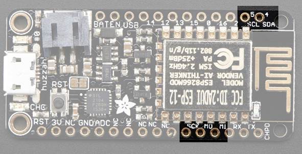
Before we proceed on connecting the two ESP8266s (the Mesh and MQTT gateways), let's look at the Adafruit Feather HUZZAH ESP8266 I2C and SPI pins.
The ESP8266 can be used to control I2C and SPI devices, sensors, outputs, etc. While this is done by 'bitbanging', it works quite well and the ESP8266 is fast enough to match 'Arduino level' speeds.
In theory you can use any pins for I2C but to make it easier for people using existing Arduino code, libraries, sketches the Adafruit Feather HUZZAH ESP8266 set up the following:
- I2C SDA = GPIO #4 (default)
- I2C SCL = GPIO #5 (default)
Likewise, you can use SPI on any pins but if you end up using 'hardware SPI' you will want to use the following:
- SPI SCK = GPIO #14 (default)
- SPI MOSI = GPIO #13 (default)
- SPI MISO = GPIO #12 (default)
GPIO #2, is also used to detect boot-mode. It also is connected to the blue LED that is near the WiFi antenna. It has a pullup resistor connected to it, and you can use it as any output (like #0) and blink the blue LED.
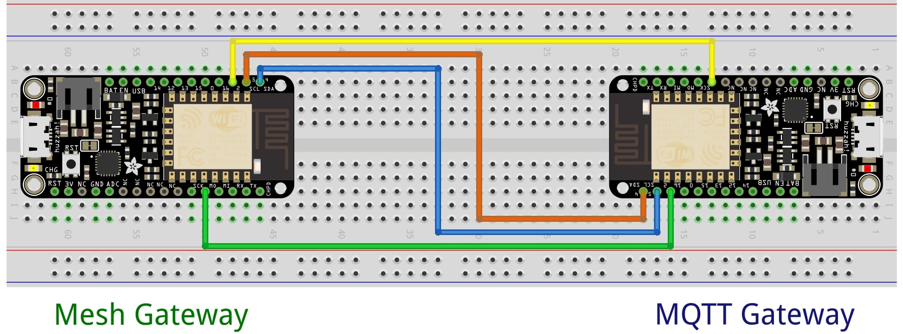
Messages sent between the two gateways are through wired jumpers which they will be connected as below.
Connections
The following are the jumper wired pin connections:
|
Mesh Gateway – ESP8266 Pin No. |
MQTT Gateway – ESP8266 Pin No. |
|
I2C SDA – GPIO #4 |
I2C SCL – GPIO #5 |
|
I2C SCL – GPIO #5 |
I2C SDA – GPIO #4 |
|
SPI SCK – GPIO #14 |
GPIO #2 |
|
GPIO #2 |
SPI SCK – GPIO #14 |
Schematics
Follow the schematic diagram to wire the 2 Adafruit Feather HUZZAH ESP8266s. Click to enlarge the diagram.