ET1530: Project - Week 11 - 13
Wireless Frames Analysis
(Adapted from: Wireshark Network Analysis 2nd Edition by Laura Chappell)
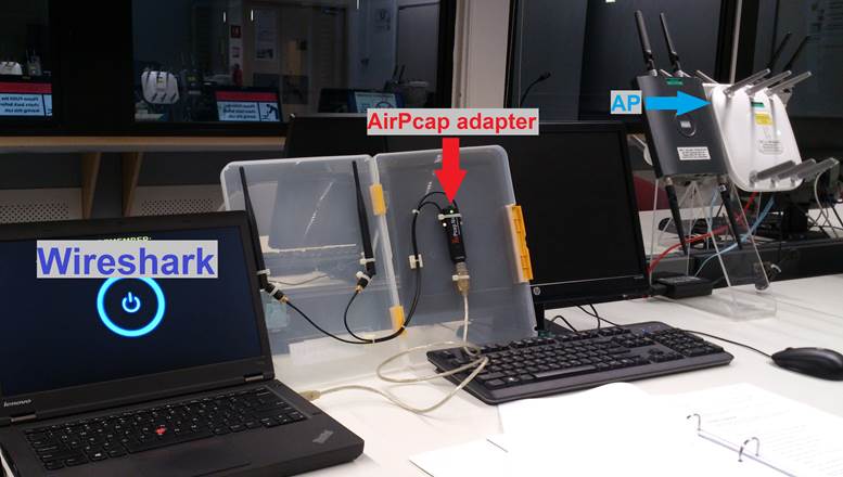
Before we can analyse wireless frames, we need to use an 802.11 adapter to capture them. To effectively analyse WLAN traffic, a Wireshark system should have a WLAN card and driver that can be put into both promiscuous mode and monitor mode.
In monitor mode, an adapter and driver pass all packets of all SSIDs from the currently selected channel up to Wireshark.
Monitor mode is not supported by WinPcap. Due to this limitation, CACE Technologies (now owned by Riverbed Technology) developed AirPcap adapters. These adapters can capture data, management and control frames; and perform multi-channel monitoring. The AirPcap aggregating adapter allows to capture on multiple AirPcap adapters (and therefore multiple channels) simultaneously.
Analyse Wireless Networks
Wireshark’s location on a wireless network is similar to the location in a wire network – start as close as possible to the complaining user. We want to learn the signal strength, packet loss rate, WLAN retry rate and round trip latency time at the location of the user who is complaining.
Once we have determined that interference is not an issue, move up to the packet level to examine the WLAN traffic such as the connection process and authentication. Examine the WLAN control and management processes to make sure everything is functioning properly before inspecting the data packets.
Understand 802.11 Traffic Basics
There are three types of 802.11 frames seen on WLANs.
|
Data |
Contains data of some sort |
|
Management |
Used to establish MAC-layer connectivity; Association Request/Responses, Probe Requests and Beacons are examples of management frames. |
|
Control |
Used to enable delivery of data and management frames; Request-to-Send (RTS) and Clear-to-Send (CTS) and ACKs are Control frames |
The management and control frames are used to enable the basic 802.11 processes. Data frames are quite simply used to transfer data across the WLAN.
Dissect the 802.11 Frame Structure
802.11 headers contain much more information than a simple Ethernet header that contains 3 fields (excluding the FCS at the end of the packet).
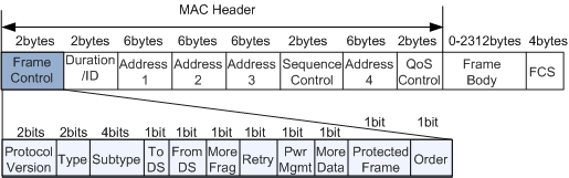
The frame body is variable length – even the maximum size is variable length depending on the encryption type in use. The IEEE 802.11 specifications state that the MSDU (MAC Service Data Unit), which is the frame payload for an 802.11 frame, has a maximum size limit of 2304 bytes.
Note that you’ll see the number 2312 listed often as the maximum frame body length of 802.11 frames. That length assumes a WEP-encrypted frame – encryption routines affect the length of the 802.11 packets.
Although the Frame Control field is only 2 bytes, it carries much information.
Frame Types
Clause 7 of the 802.11 standard documents the frame types supported by the 802.11 MAC. According to this clause, there are three frame types supported in 802.11 networks: management frames, control frames and data frames. The Type subfield in the Frame Control (FC) field of a general 802.11 frame may be 00 (management), 01 (control) or 10 (data).
Management Frame – Beacon
Beacon is a Management Frame. Beacon frames announce the existence of a network and are an important part of many network maintenance tasks. They are transmitted at regular intervals to allow mobile stations to find and identify a network, as well as match parameters for joining the network. In an infrastructure network, the access point is responsible for transmitting Beacon frames. The area in which Beacon frames appear defines the basic service area. All communication in an infrastructure network is done through an access point, so stations on the network must be close enough to hear the Beacons.
The figure below shows most the fields that can be used in a Beacon frame in the order in which they appear. Not all of the elements are present in all Beacons. Optional fields are present only when there is a reason for them to be used. The FH and DS Parameter Sets are used only when the underlying physical layer is based on frequency hopping or direct-sequence techniques. Only one physical layer can be in use at any point, so the FH and DS Parameter Sets are mutually exclusive.
The CF Parameter Set is used only in frames generated by access points that support the PCF, which is optional. The TIM element is used only in Beacons generated by access points, because only access points perform frame buffering. If the Country-specific frequency hopping extensions were to be present, they would follow the Country information element. Frequency hopping networks are much less common now, though, so I omit the frequency hopping extensions for simplicity. Likewise, the IBSS DFS element occur between the Quiet and TPC Report elements, were it to appear.
Below figure is a Beacon frame captured using AirPcap adapter. (File: AirPcap_Nx_01.pcapng)
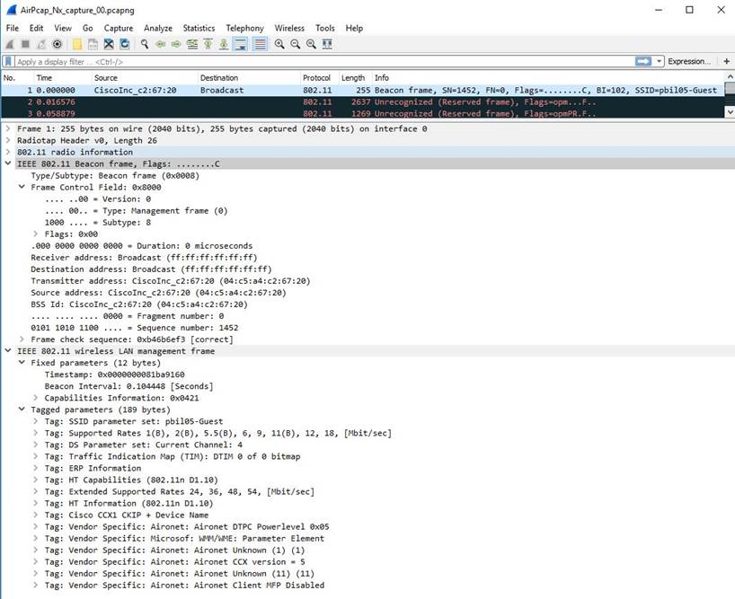
The mandatory fields (in the Payload/Frame Body) in a Beacon frame are:
1. Timestamp Field (8-byte)
Timestamp: 0x0000000081ba9160
2. Beacon Interval Field (2-byte)
Beacon Interval: 0.104448 [Seconds]
3. Capability Information Field (2-byte)
Capabilities Information: 0x0421
4. SSID Field (Variable size)
SSID parameter set: pbil05-Guest
Data Frames
Data frames are the only WLAN frame types that can be forwarded to the wired network. They are the actual carriers of application-level data. These frames can be either standard data frames or Quality of Service (QoS) data frames for devices supporting the 802.11e amendment.
Data Frame Subtypes and Subtype Field Values:
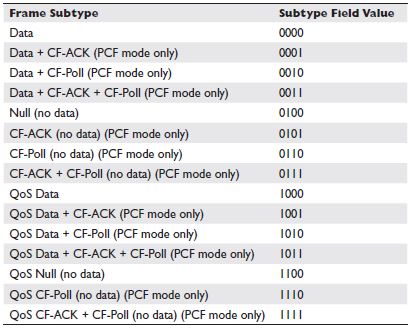
Although the IEEE 802.11 specifications state that the MAC Service Data Unit (MSDU) can be up to 2304 bytes, you will probably see smaller data frames as these frames are bridged to an Ethernet network.
Data Frames to the AP
The figure below shows the format of a frame sent from a mobile station in an infrastructure network to the access point currently serving it. The receiver address is the BSSID. In infrastructure networks, the BSSID is taken from the MAC address of the network station in the access point. Frames destined for an access point take their source/transmitter address from the network interface in the wireless station. Access points do not perform filtering, but instead use the third address to forward data to the appropriate location in the distribution system.
Example: A Capture of a Data Frame to the AP
Below is an example of a capture of a data frame to the AP with the payload of an ICMP (Echo) using AirPcap adapter. (File: AirPcap_Nx_02.pcapng)
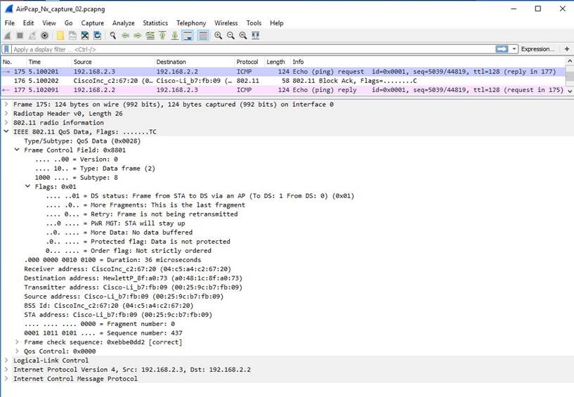
Frame Control Field (2-byte)
Ø Protocol Version: 0 = .... ..00
Ø Type: Data frame = .... 10..
Ø Subtype: 8 = 1000 ....
Ø DS status: Frame from STA to a DS via an AP (To DS: 1 From DS: 0) = .... ..01
Ø More Fragments: This is the last fragment = .... .0..
Ø Retry: Frame is not being retransmitted = .... 0...
Ø PWR MGT: STA will stay up = ...0 ....
Ø More Data: No data buffered = ..0. ....
Ø Protected flag: Data is not protected = .0.. ....
Ø Order flag: Not strictly ordered = 0... ....
Frame Control Field: 1000 1000 0000 0001 = 0x8801
Duration Field (2-byte)
Duration: 36 microseconds
Receiver Address (BSSID) Field (6-byte)
Receiver Address: 04:c5:a4:c2:67:20
Source Address Field (6-byte)
Source Address: 00:25:9c:b7:fb:09
Destination Address Field (6-byte)
Destination Address: a0:48:1c:8f:a0:73
Sequence Number Field (2-byte)
Ø Fragment number: 0 = .... .... .... 0000
Ø Sequence number: 437 = 0001 1011 0101 ....
QoS Control Field (2-byte)
QoS Control: 0x0000
Data Frame Payload (Variable)
§ Logical-Link Control (Layer 2 – Sublayer)
§ IPv4 (Layer 3 – Network)
§ ICMP (Messaging system on an IP Network)
802.11 Frame Check Sequence (FCS) Field (4-byte)
Frame check sequence: 0xebbe0dd2 [correct]
Data Frames from the AP
The figure below shows the format of a frame sent from an access point to a mobile station. As in all data frames, the first address field indicates the receiver of the frame on the wireless network, which is the frame's destination. The second address holds the transmitter address. On infrastructure networks, the transmitter address is the address of the station in the access point, which is also the BSSID. Finally, the frame indicates the source MAC address of the frame. The split between source and transmitter is necessary because the 802.11 MAC sends acknowledgments to the frame's transmitter (the access point), but higher layers send replies to the frame's source.
Nothing in the 802.11 specification forbids an access point from transmitting Null frames, but there is no reason to transmit them. Access points are forbidden from using the power-saving routines, and they can acknowledge Null frames from stations without using Null frames in response. In practice, access points send Data frames during the contention-based access period, and they send frames incorporating the CF-Poll feature during the contention-free period.
Example: A Capture of a Data Frame from the AP
Below is an example of a capture of a data frame from the AP with the payload of an ICMP (Echo reply) using AirPcap adapter. (File: AirPcap_Nx_02.pcapng)
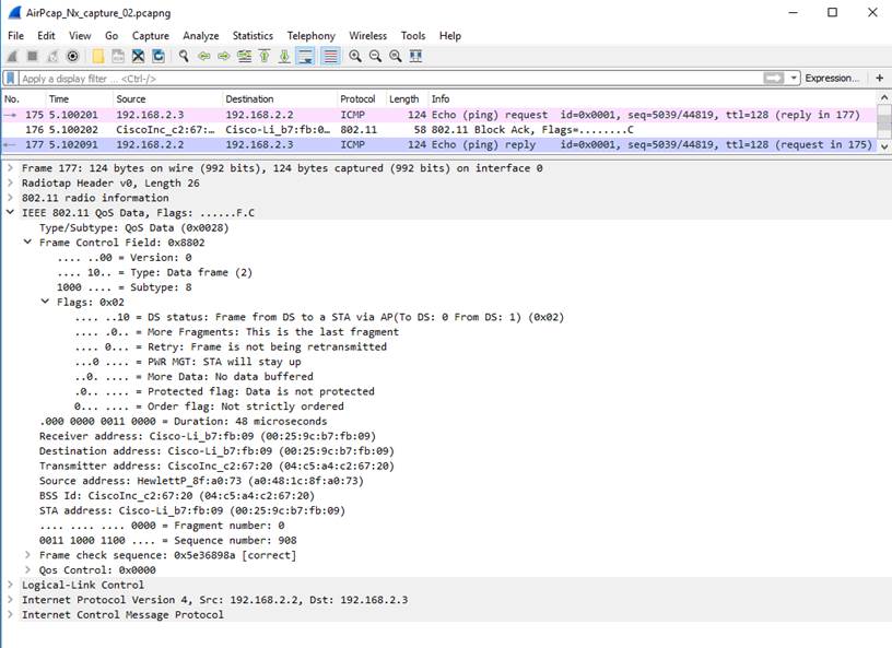
Frame Control Field (2-byte)
Ø Protocol Version: 0 = .... ..00
Ø Type: Data frame = .... 10..
Ø Subtype: 8 = 1000 ....
Ø DS status: Frame from DS to a STA via AP(To DS: 0 From DS: 1) = .... ..10
Ø More Fragments: This is the last fragment = .... .0..
Ø Retry: Frame is not being retransmitted = .... 0...
Ø PWR MGT: STA will stay up = ...0 ....
Ø More Data: No data buffered = ..0. ....
Ø Protected flag: Data is not protected = .0.. ....
Ø Order flag: Not strictly ordered = 0... ....
Frame Control Field: 1000 1000 0000 0010 = 0x8802
Duration Field (2-byte)
Duration: 48 microseconds
Destination Address Field (6-byte)
Destination Address: 00:25:9c:b7:fb:09
Transmitter Address (BSSID) Field (6-byte)
Transmitter Address: 04:c5:a4:c2:67:20
Source Address Field (6-byte)
Source Address: a0:48:1c:8f:a0:73
Sequence Number Field (2-byte)
Ø Fragment number: 0 = .... .... .... 0000
Ø Sequence number: 908 = 0011 1000 1100 ....
QoS Control Field (2-byte)
QoS Control: 0x0000
Data Frame Payload (Variable)
§ Logical-Link Control (Layer 2 – Sublayer)
§ IPv4 (Layer 3 – Network)
§ ICMP (Messaging system on an IP Network)
802.11 Frame Check Sequence (FCS) Field (4-byte)
Frame check sequence: 0x5e36898a [correct]