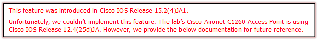
ET1530: Project - Week 11 - 13
Internal Web Authentication for Guest Access on AP Configuration
(Adapted from: http://www.cisco.com)
 |
This document describes how to configure for guest access on autonomous Access Points (APs) with the use of the internal web page that is embedded in the AP itself.
Web authentication is a Layer 3 (L3) security feature that enables the autonomous APs to block IP traffic (except DHCP and Domain Name Server (DNS)-related packets) until the guest provides a valid username and password in the web portal to which the client is redirected when a browser is opened.
With web authentication, a separate username and password must be defined for each guest. The guest is authenticated with the username and password either by the local RADIUS server or an external RADIUS server.
Connecting to Cisco Aironet C1260 Access Point to Open the CLI
We need to configure the access point locally without connecting the access point to a wired LAN. So, we connect a PC to its console port using a DB-9 to RJ-45 serial cable. Follow these steps to open the CLI by connecting to the access point console port:
Step 1![]() Connect a, nine-pin
female DB-9 to RJ-45, serial cable to the RJ-45 serial port on the access point
and to the COM port on a computer.
Connect a, nine-pin
female DB-9 to RJ-45, serial cable to the RJ-45 serial port on the access point
and to the COM port on a computer.
Step 2![]() Set up a
terminal emulator to communicate with the access point. Use the following
settings for the terminal emulator connection: 9600 baud, 8 data bits, no
parity, 1 stop bit, and no flow control.
Set up a
terminal emulator to communicate with the access point. Use the following
settings for the terminal emulator connection: 9600 baud, 8 data bits, no
parity, 1 stop bit, and no flow control.
Step 3![]() When
connected, press enter or type en to access the command prompt. Pressing enter
takes you to the user exec mode. Entering en prompts you for a password, then
takes you to the privileged exec mode. The default password is Cisco and is
case-sensitive.
When
connected, press enter or type en to access the command prompt. Pressing enter
takes you to the user exec mode. Entering en prompts you for a password, then
takes you to the privileged exec mode. The default password is Cisco and is
case-sensitive.
Note When your configuration changes are completed, you must remove the serial cable from the access point.
AP Configuration
Note: This document assumes that Bridge Virtual Interface (BVI) 1 on the AP has an IP address of 192.168.10.2 /24, and that the DHCP pool is defined internally on the AP for IP addresses 192.168.10.10 through 192.168.10.254 (IP addresses 192.168.10.1 through 192.168.10.10 are excluded).
Complete these steps in order to configure the AP for guest access:
- Add a new Service Set Identifier (SSID) , name it Guest, and configure it for web authentication:
ap(config)#dot11
ssid Guest
ap(config-ssid)#authentication open
ap(config-ssid)#web-auth
ap(config-ssid)#guest-mode
ap(config-ssid)#exit
- Create an authentication rule, where you must specify the proxy authentication protocol, and name it web_auth:
ap(config)#ip admission name web_auth proxy http
- Apply the SSID (Guest) and the authentication rule (web_auth) to the radio interface. This example uses 802.11b/g radio:
ap(config)#interface dot11radio 0
ap(config-if)#ssid Guest
ap(config-if)#ip admission web_auth
ap(confi-if)#no shut
ap(config-if)#exit
- A Define the method list that specifies where the user credentials are authenticated. Link the method list name with the web_auth authentication rule, and name it web_list:
ap(config)#ip admission name web_auth method-list authentication web_list
Complete these steps in order to configure Authentication, Authorization, and Accounting (AAA) on the AP and local RADIUS server, and link the method list with the local RADIUS server on the AP:
- Enable AAA:
ap(config)#aaa new-model
- Configure the local RADIUS server:
ap(config)#radius-server
local
ap(config-radsrv)#nas 192.168.10.2 key cisco
ap(config-radsrv)#exit
- Create the guest accounts, and specify their lifetime (in minutes). Create one user account with a username and password of user1, and set the lifetime value to 60 minutes:
ap(config)#dot11 guest
ap(config-guest-mode)#username user1 lifetime 60 password user1
ap(config-guest-mode)#exit
ap(config)#
You can create other users with the same process.
- Define the AP as a RADIUS server:
ap(config)#radius-server host 192.168.10.2 auth-port 1812 acct-port 1813 key cisco
- Link the web authentication list with the local server:
ap(config)#aaa authentication login web_list group radius
Configure the Wireless Client
Complete these steps in order to configure the wireless client:
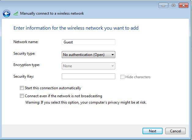
- In order to configure the wireless network on your windows supplicant utility with the SSID named Guest, navigate to Network and Internet > Manage Wireless Networks, and click Add.
- Select Manually connect to
a wireless network, and enter the required information, as shown in
this image:
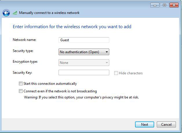
- Click Next.
After the configuration is complete, the client can connect to the SSID normally, and you see this on the AP console:
%DOT11-6-ASSOC:
Interface Dot11Radio0, Station ap 0027.10e1.9880
Associated KEY_MGMT[NONE]
ap#show dot11 ass
802.11 Client Stations on Dot11Radio0:
SSID [Guest] :
MAC Address IP address IPV6 address
Device Name Parent State
0027.10e1.9880
0.0.0.0 :: ccx-client
ap self Assoc
The client has a dynamic IP address of 192.168.10.11. However, when you attempt to ping the IP address of the client, it fails because the client is not fully authenticated:
ap#PING 192.168.10.11
Type escape sequence to abort.
Sending 5, 100-byte ICMP Echos to 192.168.10.11, timeout is 2 seconds:
.....
Success rate is 0 percent (0/5)
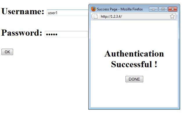
If the client opens a browser, and attempts to reach http://1.2.3.4 for example, the client is redirected to the internal login page:
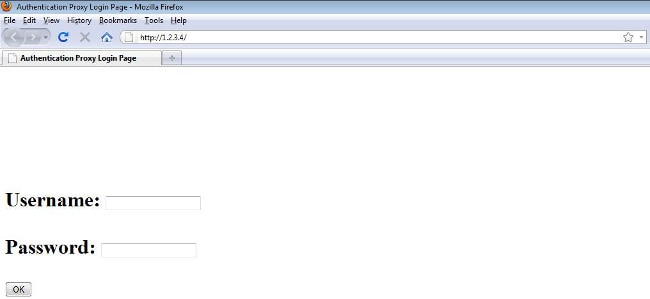
Note: This test is completed with a random IP address entered directly (here the URL entered is 1.2.3.4) without the need for translation of a URL through the DNS, because the DNS was not used in the test. In normal scenarios, the user enters the home page URL, and the DNS traffic is allowed until the client sends the HTTP GET message to the resolved address, which is intercepted by the AP. The AP spoofs the web site address, and redirects the client to the login page stored internally.
Once the client is redirected to the login page, the user credentials are entered and verified against the local RADIUS server, as per the AP configuration. After successful authentication, the traffic that comes from and goes to the client is fully allowed.
Here is the message that is sent to the user after successful authentication:
After successful authentication, you can view the client IP information:
ap#show dot11 ass
802.11 Client Stations on Dot11Radio0:
SSID [Guest] :
MAC Address IP address IPV6 address
Device Name Parent State
0027.10e1.9880 192.168.10.11 ::
ccx-client ap self Assoc
Pings to the client after successful authentication is complete should work properly:
ap#ping 192.168.10.11
Type escape sequence to abort.
Sending 5, 100-byte ICMP Echos to 192.168.10.11, timeout is 2 seconds:
!!!!!
Success rate is 100 percent (5/5), round-trip min/avg/max = 1/3/6 ms
There is currently no specific troubleshooting information available for this configuration.
Note: Roaming between APs during web authentication does not provide a smooth experience, because the clients must log in to each new AP to which they connect.
Similar to the IOS on routers or switches, you can customize your page with a custom file; however, it is not possible to redirect to an external web page.
Use these commands in order to customize the portal files:
- ip admission proxy http login page file
- ip admission proxy http expired page file
- ip admission proxy http success page file
- ip admission proxy http failure page file