EG254S: IoT System Project - IoT Data  IoT Security

Making Sense of the Touch Sensor Data

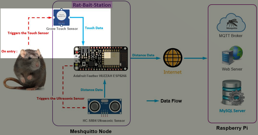
The Grove – Touch Sensor is fixed at the entrance of the Rat-Bait-Station. When a rat enters the station, it triggers the capacitive touch sensor.

We shall program the Touch Sensor in the Arduino sketch for the Meshquitto Node. Open the meshquittoNode.ino file (the Meshquitto Node sketch) using the Arduino IDE.

Define the TOUCHPIN for the touch sensor:

// Define GPIO pins

#define   TOUCHPIN        16            // Pin for capacitive touch sensor

#define   LED_PIN         0             // Pin for the pin for the Onboard red LED

#define   LED_TOPIC       "LED1"

#define   TRIGGER         12            // GPIO pin for HC-SR04 Ultrasonic Sensor's Trig pin

#define   ECHO            13            // GPIO pin for HC-SR04 Ultrasonic Sensor's Echo pin

#define   DIST_TOPIC      "RatBS001"

The touch sensor is activated upon a rat entering the station, which gives the sensorValue equal to 1. I will use the IF statement. When the sensorValue = 1 is TRUE, the ESP8266 onboard red LED will light up. There will be a delay of 3 seconds before the Ultrasonic sensor activates.

When there is no touch sensing received from the capacitive touch sensor, the sensorValue is always equal to 0. Therefore, using the IF statement, when sensorValue = 1 is FALSE (which is the ELSE statement), the ESP8266 onboard red LED will be off and there will be no Ultrasonic sensing activity. Hence, any pests entering the Rat-Bait-Station will not trigger the ultrasonic sensor without able to trigger the touch sensor.

I had integrated the touch sensor code (highlighted in blue) with the Meshquitto Node sketch:

/************************************************************************/

/* Checks if SEND_INTERVAL has passed and if true, reads from           */

/* Ultrasonic sensor and publishes distance                             */

/*~~~~~~~~~~~~~~~~~~~~~~~~~~~~~~~~~~~~~~~~~~~~~~~~~~~~~~~~~~~~~~~~~~~~~~*/

int readDist()                                   

/*~~~~~~~~~~~~~~~~~~~~~~~~~~~~~~~~~~~~~~~~~~~~~~~~~~~~~~~~~~~~~~~~~~~~~~*/

{

  if((millis()-lastMsg>=SEND_INTERVAL)){

    lastMsg = millis();


    Serial.print("Touch: ");

    int sensorValue = digitalRead(TOUCHPIN);

    if(sensorValue==1)

    {

        digitalWrite(LED_PIN, LOW);     // Turn on red LED - note the LED of GPIO pin0 is reverse wired

        Serial.println("ON");           // so setting the pin LOW will turn the LED on


        delay(3000);                    // waits for 3 seconds

        Serial.print(" Initiating motion sensor... ");

        // Clears the TRIGGER of HC-SR04 Ultrasonic sensor

        digitalWrite(TRIGGER, LOW); 

        delayMicroseconds(2);


        // Sets the TRIGGER of HC-SR04 Ultrasonic sensor on HIGH state for 10 micro seconds 

        digitalWrite(TRIGGER, HIGH);

        delayMicroseconds(10);

        digitalWrite(TRIGGER, LOW);


        // Reads the ECHO of HC-SR04 Ultrasonic sensor, returns the sound wave travel time in microseconds

        long duration = pulseIn(ECHO, HIGH);

        Serial.print(" Distance: ");

        // Calculating the distance (in cm) based on the speed of sound

        int distance= duration*0.0343/2;

        // Prints the distance on the Serial Monitor

        Serial.print(distance); Serial.println(" cm");


        char dist[] = "";

        dtostrf(distance, 1, 0, dist);

        DynamicJsonBuffer jsonBufferFS;

        JsonObject& rootFS2 = jsonBufferFS.createObject();

        rootFS2["topic"] = DIST_TOPIC;

        rootFS2["payload"] = String(dist);

        String json_msg;

        rootFS2.printTo(json_msg);

        Serial.println("Sending.....");

        uint32_t dest = GW_ID;

        String encrypted_msg = AES_encrypt(json_msg, AES_KEY);

        mesh.sendSingle( dest, encrypted_msg );


    }

    else

    {

        digitalWrite(LED_PIN, HIGH);      // Turn off red LED - note the LED of GPIO pin0 is reverse wired

        Serial.println("OFF");            // so setting the pin HIGH will turn the LED off

    }

  }

  return 0;

}

Under the void setup():

void setup() {

  Serial.begin(115200);                    // Starts the serial communication

  Serial.print("Chip ID: "); Serial.println(ESP.getChipId());

  pinMode( LED_PIN, OUTPUT );              // Sets digital pin connected to onboard red LED as output

  digitalWrite(LED_PIN, HIGH);             // Sets initial state of onboard red LED to off, reverse wired

  pinMode(TOUCHPIN, INPUT);

  pinMode(TRIGGER, OUTPUT);                // Sets the TRIGGER as an Output for HC-SR04 Ultrasonic Sensor

  pinMode(ECHO, INPUT);                    // Sets the ECHO as an Input for HC-SR04 Ultrasonic Sensor

Conclusion

The Grove – Touch Sensor's data is the easiest and simplest to handle with. It produces numeric data consisting of only two integers which is 0 and 1. The value 0 indicates the touch sensor is in detection mode. When the touch pad of the touch sensor is touched, it activates the capacitive sensing circuit and gives the value 1 until the touch is lifted off from the touch pad.

The Touch Sensor Data is used on the go. When the data indicates the value 1, a rat is detected entering the Rat-Bait-Station and followed by activating the ultrasonic sensor. Hence, it is not necessary to store the data.